We may earn a commission from purchases through links in this article, at no extra cost to you. How we earn
Kinematic & Electrical Findings
Chassis Stiffness
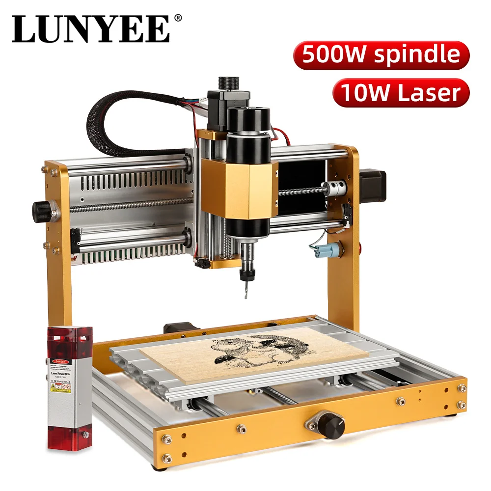
The 3018 Pro Max replaces traditional bakelite plates with an all-metal aluminum structure, reducing chassis flex during light milling in wood, acrylic, and copper-clad PCBs.
Power Stage Realities
Achieving true 500W continuous output requires a dedicated 48V supply drawing over 10A; standard bundled 24V desktop adapters deliver lower continuous power during heavy passes.
Open-Loop Risks
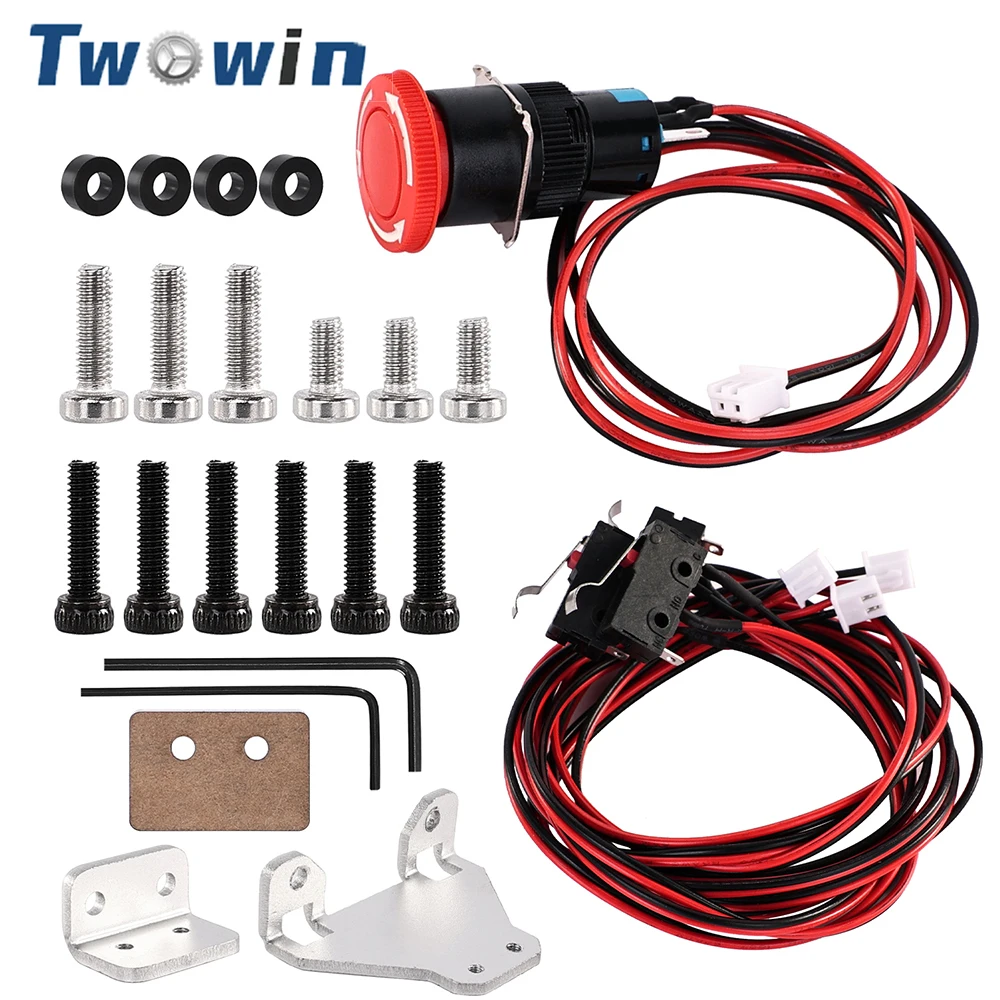
Standard base packages omit physical limit switches and hardware E-stops, making aftermarket endstop integration critical for repeatable homing and crash prevention.
Base Platform Architecture
The standard CNC 3018 Pro Max baseline package combines an aluminum structural skeleton with a high-speed DC spindle and an open-source GRBL controller across a nominal 300 x 180 mm working envelope.
While suitable for circuit isolation routing and soft material carving, prospective buyers must evaluate actual power headroom and add external limit switches for safe coordinate reference homing.
Component Specifications & Ecosystem Trade-Offs
| Product | Primary Functional Role | Structural & Operational Trade-Off |
|---|---|---|
| CNC 3018 Pro Max CNC Milling Machine 500W Spindle GRBL Control… | Full machining platform; 500W-rated spindle, GRBL board, all-metal frame. | Base package lacks factory physical limit switches and E-stop hardware. |
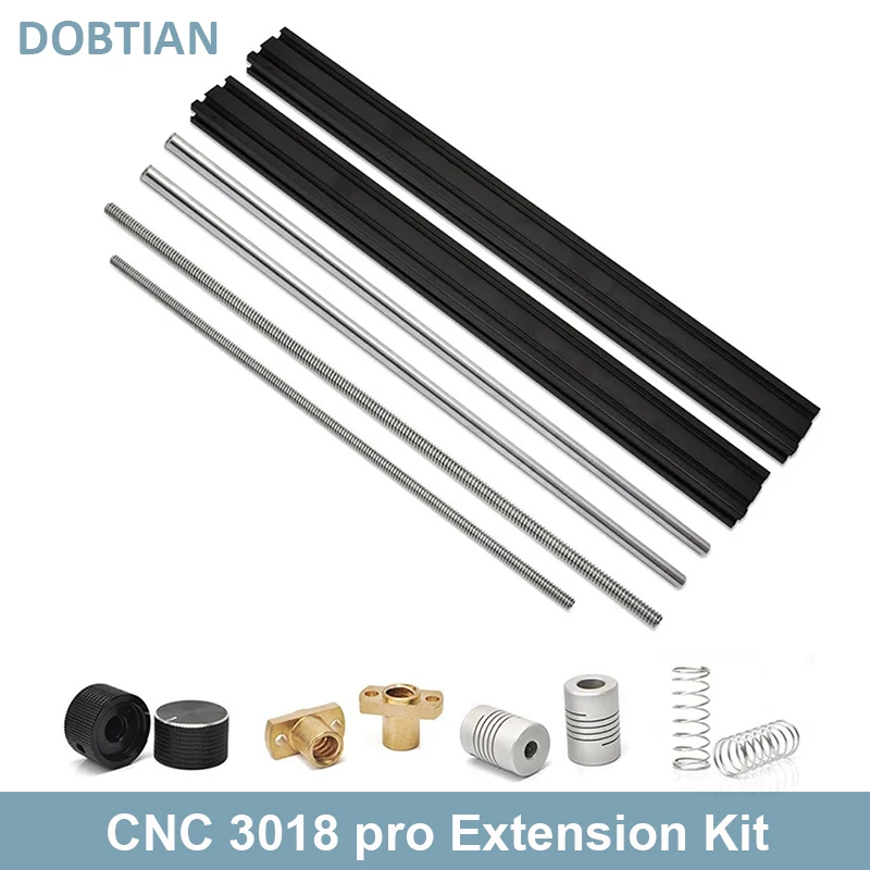
| Upgrade Kit X-Axis Y-Axis Extension Kit for DIY CNC 3018 Pro… | Doubles Y-axis travel envelope for large workpieces and laser projects. | Longer unsupported rods increase mid-span flex under heavy cutting loads. |
| CNC 3018 / 3018-Pro/MAX Z Axis 775 Spindle Motor Drill Chunk… | Complete replacement Z assembly with drill chuck and motor mount. | Drill chuck exhibits higher radial runout than dedicated ER11 collets. |
| Limit Switch Emergency Stop Switch Part Laser Engraving Machine… | Pre-fitted rail brackets for structured homing and spindle safety stops. | Requires manual firmware configuration ($21/$22 parameters). |
| Limit Switch with E-Stop Button Kit 6 Micro Limit Switches with… | Dual-limit coverage (Min/Max) across X, Y, and Z axes on 2-pin headers. | Requires custom bracket alignment on certain aluminum extrusion profiles. |
Key Upgrades and Safety Accessories


Essential GRBL Safety & Calibration Setup
Wire Limit Switches
Connect 2-pin micro switches to the X, Y, and Z endstop pin headers on the GRBL control board.
Enable Hard Limits
Send command $21=1 via G-code console to trigger an immediate halt upon physical switch closure.
Configure Homing Cycles
Set $22=1 to enable repeatable automated machine coordinate homing cycles prior to running jobs.
Verify Depth and Feed Rates
Program shallow depth of cut passes and appropriate feed-per-tooth values to maintain continuous spindle velocity.
Technical Audit & Motion Verification
Known facts
Standard 3018 Pro Max travel provides a nominal 300 x 180 mm machining envelope.
The 3040 extension kit extends the physical Y-axis travel to roughly 300 x 400 mm.
Continuous 500W DC motor output requires a 48V power supply capable of delivering over 10A.
Analysis
Extended steel guide rods on the 3040 frame experience increased mid-span deflection under aggressive cutting loads.
Standard drill chucks introduce greater radial tool runout than precision-ground ER11 collet systems.
Uncertainties
Specific bundled power supply ratings vary across individual marketplace sellers and SKUs.
Mechanical & Practical Limitations
- Base 3018 Pro Max kits do not include factory hardware limit switches or E-stop buttons.
- Drill chuck spindle configurations are unsuitable for high-precision PCB trace isolation due to radial runout.
- Extended Y-axis 3040 configurations require conservative feed rates to mitigate torsional shaft deflection.